
Your cart is currently empty!
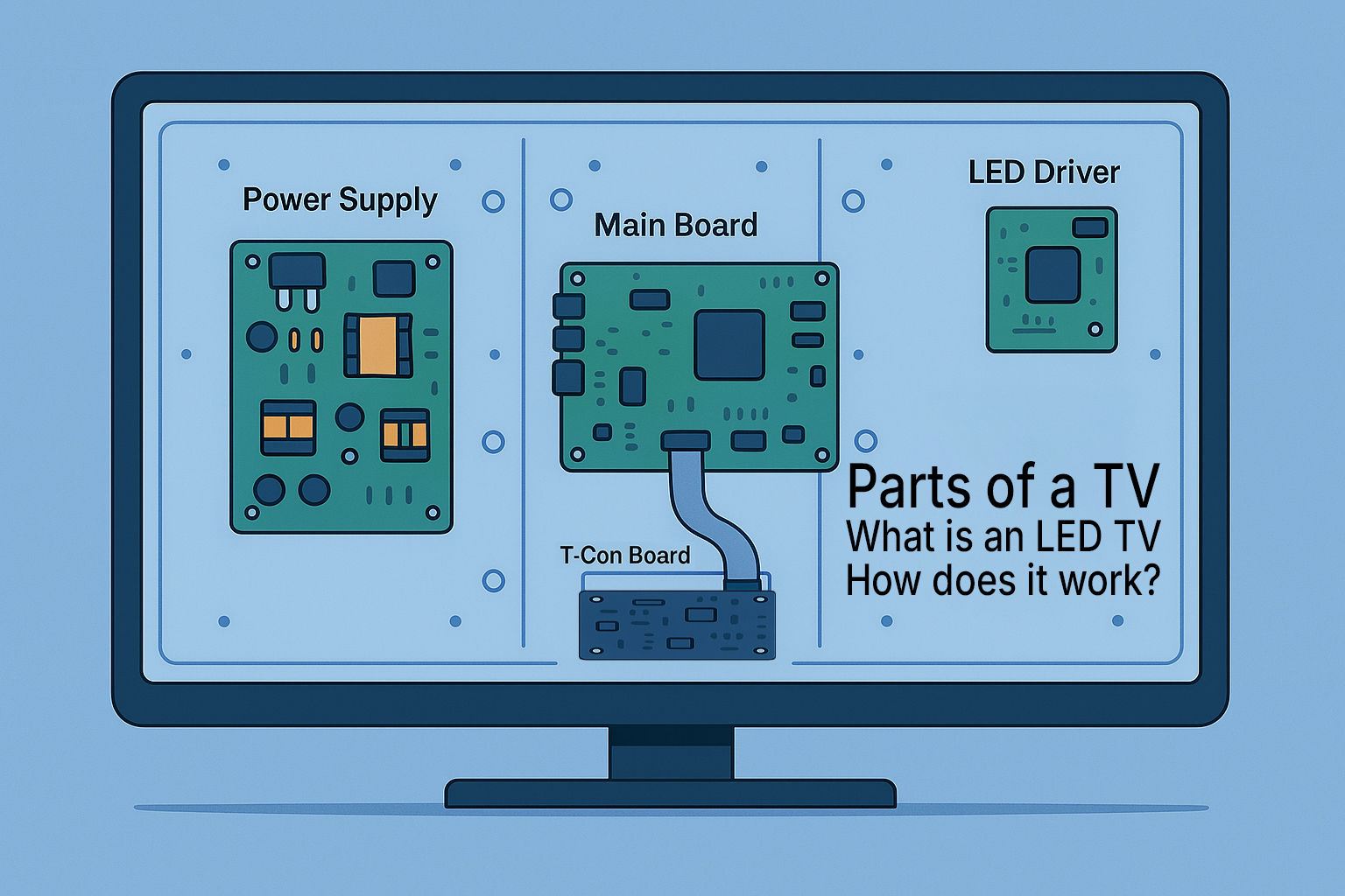
An LED TV combines a traditional LCD panel with energy‑efficient light‑emitting diodes (LEDs) for backlighting, giving you brighter images and slimmer designs. But what exactly is an LED TV, and how does it work?
Inside every set you’ll find a handful of critical parts—like the power supply board that converts mains power, the mainboard that processes your HDMI and smart‑TV signals, the T‑Con board that controls pixel timing, and the LED driver that powers the backlight—working in concert to deliver crisp, vibrant picture and sound.
Understanding these parts of a TV is the key to diagnosing problems, tackling DIY repairs, or simply knowing which replacement components you need. In the sections below, we’ll explain what an LED TV is, break down each essential component, and link you directly to ePartsy’s tested replacement parts so you can get your screen back up and running.
Why Understanding LED TV Parts Matters
Knowing the parts of a TV lets you:
- Diagnose issues faster
- Order the right TV parts without guessing
- Save money by replacing only the faulty board
- Feel confident tackling DIY TV repairs
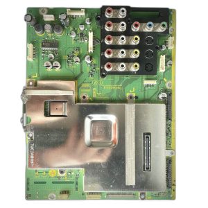
1. Power Supply Board (TV Power Supply)
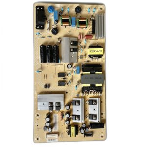
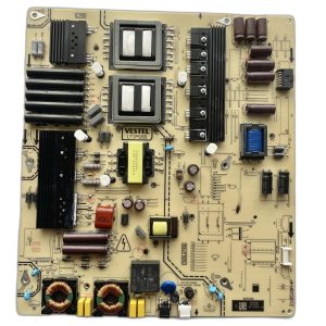
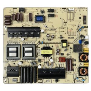
Also known as: PSU, Power Board
What it does: The power supply board is the heart of your LED TV’s electrical system. It takes the high‑voltage AC (120 VAC in North America or 230 VAC in many other regions) from your wall outlet and transforms it into multiple low‑voltage DC rails—typically including 3.3 V, 5 V, 12 V, and sometimes 24 V—that feed every other circuit in the TV.
How Power Supplies Work:
- Input Stage & Surge Protection:
- Incoming AC passes through an EMI filter (to block electrical noise) and a surge protector (MOV or fuse) to guard against spikes.
- Rectification & Filtering:
- A bridge rectifier converts AC into pulsating DC. Large electrolytic capacitors smooth this into a steadier DC “bus” voltage.
- Switch‑Mode Regulation:
- A PWM (pulse‑width modulation) controller chip drives high‑speed MOSFETs or transistors, chopping the DC bus into controlled pulses.
- These pulses feed a high‑frequency transformer, which steps down voltage with much smaller coils than a traditional transformer.
- Secondary Rectification & Regulation:
- On the low‑voltage side, fast diodes and additional capacitors convert the transformer output back into clean DC rails.
- Dedicated regulator ICs or zener diodes fine‑tune each rail to its precise voltage.
- Protections & Monitoring:
- The board often includes over‑current, over‑voltage, and thermal shutdown features.
- A feedback loop from the secondary side tells the PWM controller to adjust duty cycle and maintain stable output.
Symptoms of failure:
TV Won’t Power On
- What you see: Pressing the power button (or using the remote) does nothing—no click, no backlight, no standby LED.
- Possible causes on the PSU:
- Blown fuse or surge protector (MOV): A one‑time spike can blow the input fuse or MOV, cutting all power.
- Failed startup circuit: The PWM controller or its bias circuit may not be receiving the initial voltage it needs to begin switching.
- Open primary winding: A damaged transformer winding means no energy transfer to the secondary side.
- How to diagnose:
- Check the fuse for continuity with a multimeter.
- Probe the standby rail (often 5 VSB) to see if it’s present—if it’s missing, the controller can’t start.
- Inspect for visual damage like burnt traces or blown components around the AC input.
Quick fix: Replacing a blown fuse or MOV may restore function—but always investigate the root surge or short that caused the blow.
Intermittent Shutdowns or Clicking Sounds
- What you see/hear: The TV turns on normally, shows picture and sound, then abruptly powers off (sometimes repeatedly). You might hear a rapid “click‑click‑click” from inside.
- Possible causes on the PSU:
- Over‑current or thermal shutdown: A failing component overheats or draws too much current, triggering built‑in protection to cut off output.
- Weak capacitors: As electrolytics age, their capacitance drops and ESR (equivalent series resistance) rises, causing the board to hiccup under load.
- Faulty feedback loop: If the secondary‑to‑primary feedback signal is erratic, the controller can’t regulate output properly.
- How to diagnose:
- Listen for the click pattern: Rapid clicks often mean the board is trying—and failing—to start.
- Feel for heat: Carefully touch (or use a non‑contact thermometer) near the PWM controller and capacitors.
- Measure output rails during operation; watch for voltage collapse just before shutdown.
Quick fix: Swapping out bulging or leaky capacitors often cures intermittent shutdowns. Ensure any replacement caps match the original voltage and temperature ratings.
No Backlight but Standby Light Is On
- What you see: The TV powers on (standby LED goes off), you hear sound or menu navigation beeps, but the screen remains completely dark.
- Possible causes on the PSU:
- Backlight rail failure: Many PSUs generate a separate “BL” (backlight) rail; if that voltage is missing, the LEDs won’t illuminate.
- Shorted LED driver stage: Some designs integrate the backlight inverter on the PSU; a short here can pull down the entire board.
- Protection mode: The PSU may detect an open or short in the LED string and disable the rail to prevent damage.
- How to diagnose:
- Shine a flashlight at an angle on the screen—if you see a faint image, the mainboard is working and only the backlight is out.
- Measure the backlight voltage test point (often around 12 V to 24 V) on the PSU.
- Inspect the backlight fuse (if present) and the inverter components for shorts.
Quick fix: If the backlight rail is the only fault, replacing the PSU (or just the inverter section) will restore illumination without touching the LCD panel.
2. Main Board (TV Mainboard)
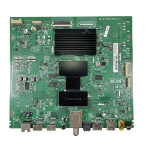
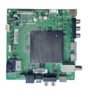
Also known as: Motherboard
What it does: The main board is the TV’s brain. It receives all your input signals—HDMI, USB media, RF tuner, Ethernet/WiFi for smart‑TV features—and decodes them into raw video and audio data. A system‑on‑chip (SoC) or dedicated decoder hardware handles video compression formats (MPEG, H.264, HEVC), while an audio codec processes sound streams (AAC, AC‑3, DTS).
The board’s CPU runs the TV’s firmware or smart‑OS, manages memory/storage (for apps and settings), and orchestrates everything from on‑screen menus to network updates. Once decoded, it sends pixel‑perfect video to the T‑Con board via LVDS or eDP, and routes audio to the amplifier or speaker board.
How Main Boards Work:
- Signal Input & Reception:
- HDMI Ports: TMDS receivers capture digital video/audio from set‑top boxes, game consoles, and streaming sticks.
- USB Host Controller: Interfaces with flash drives or external HDDs, providing file‑system access to media players.
- Tuner & RF Front‑End: Demodulates over‑the‑air or cable signals (ATSC, QAM, DVB) into transport streams.
- Network Interfaces: Ethernet PHY or WiFi module connects to home networks for streaming and firmware OTA updates.
- Demultiplexing & Video Decoding:
- Stream Demux: Separates combined transport streams into individual audio, video, and subtitle tracks.
- Hardware Video Decoder: Dedicated ASIC decodes compressed video (e.g., H.264, HEVC) in real time.
- Image Processing Pipeline: Performs deinterlacing, scaling, color‑space conversion, noise reduction, and HDR tone mapping.
- Audio Decoding & DSP:
- Audio Codec IC: Decodes Dolby Digital, DTS, AAC, and PCM streams.
- Digital Signal Processor: Applies equalization, surround‑sound virtualization, volume leveling, and lip‑sync correction.
- System Control & Smart OS:
- SoC CPU & Memory: Runs embedded Linux or proprietary smart‑TV OS, handles user interface, app execution, and network services.
- Flash Storage: Holds firmware, app binaries, and user settings.
- Watchdog & Bootloader: Ensures reliable startup and safe firmware updates.
- Signal Distribution & Output:
- Video Output: Sends processed pixel data over LVDS/eDP ribbon cables to the T‑Con board, which drives the LCD panel.
- Audio Output: Routes line‑level audio to an onboard amplifier or separate audio board.
- Control Buses: Communicates with IR sensor board, button panel, and backlight inverter via I²C, SPI, or GPIO lines.
- Protections & Monitoring:
- Voltage Monitoring: Ensures all internal rails (3.3 V, 1.2 V, etc.) remain within safe ranges.
- Thermal Sensors: Throttles or shuts down the SoC if temperatures exceed limits.
- Firmware Recovery: Some boards include dual‑bank flash or USB recovery modes for failed updates.
Symptoms of failure:
“No Signal” on All Inputs
- What you see: The screen stays black or displays “No Signal” no matter which HDMI or input source is selected.
- Possible causes on the PSU:
- Mainboard not receiving power: The PSU may not be delivering standby or logic voltage (e.g., 3.3 V or 5 V) to the mainboard.
- Failed 12 V rail: Some input boards require a dedicated 12 V feed from the PSU to power HDMI switching ICs or AV processors.
- Protection mode active: A detected fault may shut down certain rails while leaving others active, resulting in partial system startup.
- How to diagnose:
- Check voltage outputs at the PSU connector—look for missing or unstable rails (often labeled on the board).
- Look for LED indicators on the mainboard—no lights can indicate missing standby power.
- Inspect the HDMI board or input selector section for bulging caps or burnt traces.
Quick fix: If the mainboard isn’t receiving voltage, replacing the PSU can often restore signal functionality—verify all outputs before condemning the board.
Frozen Menus or OS Crashes
- What you see: The TV boots up, but menus freeze, apps crash, or the system becomes unresponsive after a few seconds.
- Possible causes on the PSU:
- Fluctuating voltage rails: If the 3.3 V or 5 V rails sag under load, the processor may crash or freeze during operation.
- Noise or ripple: Bad capacitors can cause power instability, which is especially problematic for digital logic circuits.
- Thermal instability: Faulty regulation components may operate normally when cold, but drift or shut down when hot.
- How to diagnose:
- Measure rail voltages at startup and after several minutes of use—look for dips or oscillations.
- Use an oscilloscope if available to check for ripple or noise on the logic rails.
- Test with the mainboard isolated (no panel connected) to see if it behaves more stably without load.
Quick fix: Replacing aging capacitors on the PSU often eliminates logic crashes—look for low ESR, high-temp replacements rated at 105 °C.
Audio Plays but No Picture
- What you see: The TV powers on, plays audio normally, and responds to input—yet the screen stays black or backlighted with no image.
- Possible causes on the PSU:
- Missing panel voltage: The T‑CON or panel may require a dedicated rail (e.g., 12 V or 15 V) from the PSU to function.
- Faulty T‑CON fuse or driver IC: The PSU may be working fine, but a short on the panel interface prevents picture generation.
- Partial failure of output section: Some PSU rails may function while others (e.g., for video or panel logic) are absent.
- How to diagnose:
- Measure panel supply rails at the T‑CON input connector—verify correct voltage and stability.
- Check for screen glow or faint patterns under bright light—if visible, the issue may be signal-related, not power.
- Probe the PSU output connector with a multimeter and check for missing rails labeled “PANEL,” “AVDD,” or similar.
Quick fix: If panel voltage is absent but audio works, replacing or repairing the PSU often brings back the picture—verify T‑CON functionality if voltages are present.
3. T‑Con Board (Timing Control Board)
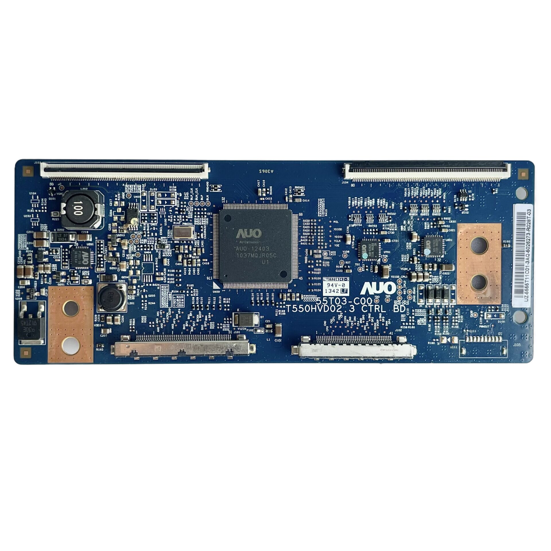
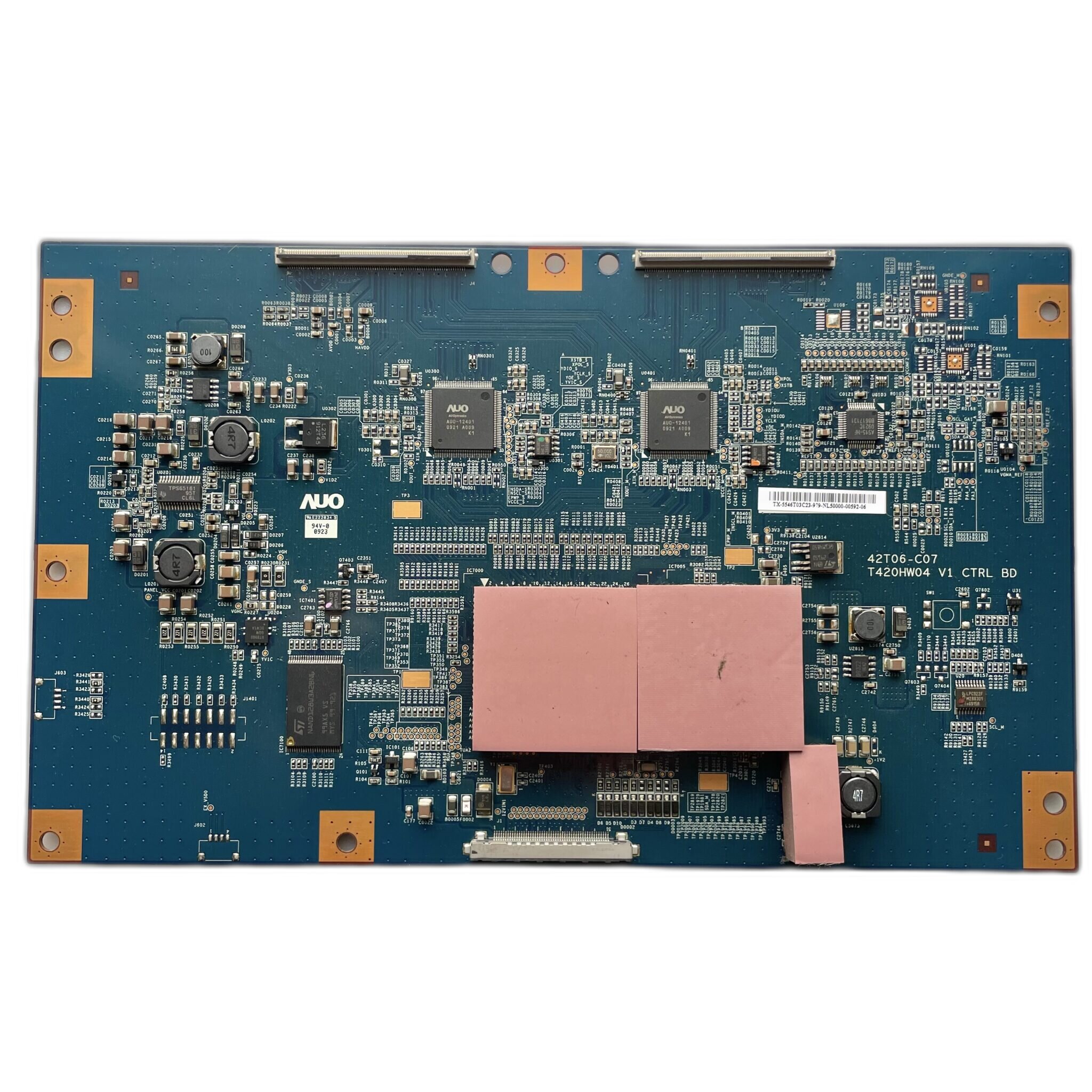
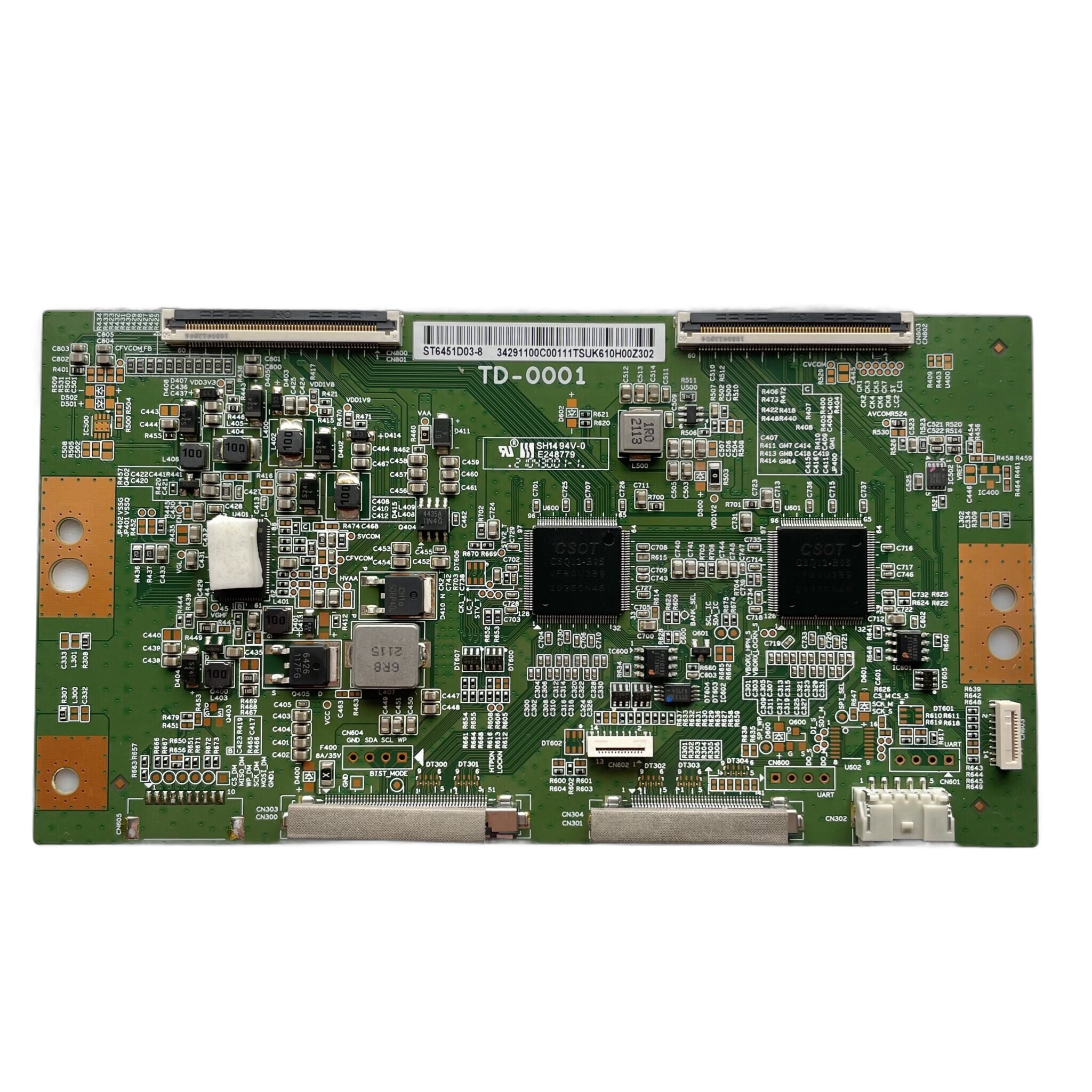
Also known as: Timing Board
What it does: The T‑Con (Timing Controller) board is responsible for converting raw video signals from the main board into tightly synchronized electrical impulses that control the LCD panel’s row and column drivers. It serves as the middleman between digital image processing and the physical display, ensuring each pixel lights up at the right moment with the correct color and intensity.
Located either as a separate board or embedded into the panel, the T‑Con interprets LVDS or eDP signals and reshapes them into the high-speed gate and source drive signals required by the panel’s internal circuitry. Timing precision is critical: a faulty T‑Con can result in flickering, vertical lines, frozen images, or a completely blank screen despite proper power and signal input.
How T‑Con Boards Work:
- Input Signal Handling:
- LVDS Receiver or eDP Interface: Accepts serialized video data streams from the mainboard over a thin ribbon cable.
- Timing Controller IC: Deserializes the data and reconstructs horizontal and vertical sync pulses, pixel clocks, and frame buffers.
- Frame Timing & Distribution:
- Gate Driver Control: Sends horizontal scanning pulses to row drivers to address individual rows of pixels.
- Source Driver Control: Aligns vertical signal data for each column based on the current row being addressed.
- VCOM & Gamma Reference: Controls pixel biasing voltages and voltage steps for grayscale accuracy and uniformity.
- Panel Configuration Data:
- EDID EEPROM or OTP Memory: Stores panel‑specific timing parameters and voltage curves preprogrammed by the factory.
- Gamma LUT Tables: Provides reference values for linear color output across varying brightness levels.
- Error Handling & Fail-Safes:
- Gate/Source Voltage Protection: Monitors output voltages to prevent panel damage from short circuits or overdrive conditions.
- Thermal Shutdown: Some T‑Con ICs include built-in protection if surface temperatures exceed safe operating limits.
- Signal Output to Panel:
- COF (Chip-on-Film) Ribbon Output: T‑Con output signals travel via ultra‑thin flexible ribbon cables directly bonded to the LCD glass or driver boards.
- Data Drive Synchronization: Ensures all pixels are updated row by row within microseconds for a clear, flicker-free image.
Symptoms of failure:
Vertical or Horizontal Lines
- What you see: Thin lines appear across the screen, often evenly spaced or flickering, and may disappear or change with pressure or temperature.
- Possible causes on the T-CON board:
- Driver IC failure: A failing IC on the T-CON board can corrupt image signals to the panel.
- Loose or oxidized ribbon cable: The LVDS or panel ribbon connectors may have poor contact, causing intermittent signal issues.
- Shorted data lines: Electrostatic damage or corrosion can short signal paths, leading to consistent line artifacts.
- How to diagnose:
- Press gently on the edges of the screen or cable connectors—if lines change or disappear, the issue may be mechanical.
- Inspect ribbon connectors for oxidation, misalignment, or damage—clean and reseat as needed.
- Check ICs on the T-CON board for overheating or visible damage.
Quick fix: Replacing or reflowing the T-CON board often resolves line issues—ensure panel ribbons are clean and seated firmly.
Flickering or Distorted Image
- What you see: The screen flickers, shows random colors or static, or produces a “solarized” or posterized image.
- Possible causes on the T-CON board:
- Clock/data sync failure: A timing issue between the mainboard and panel can cause frame artifacts or instability.
- Corrupt EEPROM data: T-CON firmware corruption can distort image processing functions.
- Power delivery fault: The T-CON board may not be receiving stable voltage from the PSU.
- How to diagnose:
- Measure voltage rails (e.g., VGH, VGL, AVDD) on the T-CON board for stability and presence.
- Test with a known-good mainboard to rule out signal issues upstream.
- Inspect for firmware or part number mismatches if the T-CON was replaced or swapped.
Quick fix: Swap the T-CON with a known-good matching board—if voltage rails are stable and symptoms persist, suspect panel or mainboard.
Black Screen with Audio Intact
- What you see: The TV turns on, audio works, but there is no image—sometimes the backlight is active, other times the screen is fully black.
- Possible causes on the T-CON board:
- No panel drive voltage: Missing AVDD, VGH, or VGL can prevent the panel from displaying an image.
- Blown fuse: A small surface-mounted fuse on the T-CON may open, often due to a short or surge.
- LVDS signal loss: A bad connection from the mainboard can cause a total image failure, even with active power rails.
- How to diagnose:
- Check T-CON fuses and power rails using a multimeter—replace fuse if open and no shorts exist.
- Shine a flashlight at the screen from an angle—if faint menu elements are visible, the issue may be with panel drive voltages.
- Check ribbon cables for signs of heat damage or loose fit at both ends.
Quick fix: Replacing the T-CON board or restoring power via fuse replacement can restore image—be sure to check for shorts before powering on.
4. LED Driver (Backlight Inverter)
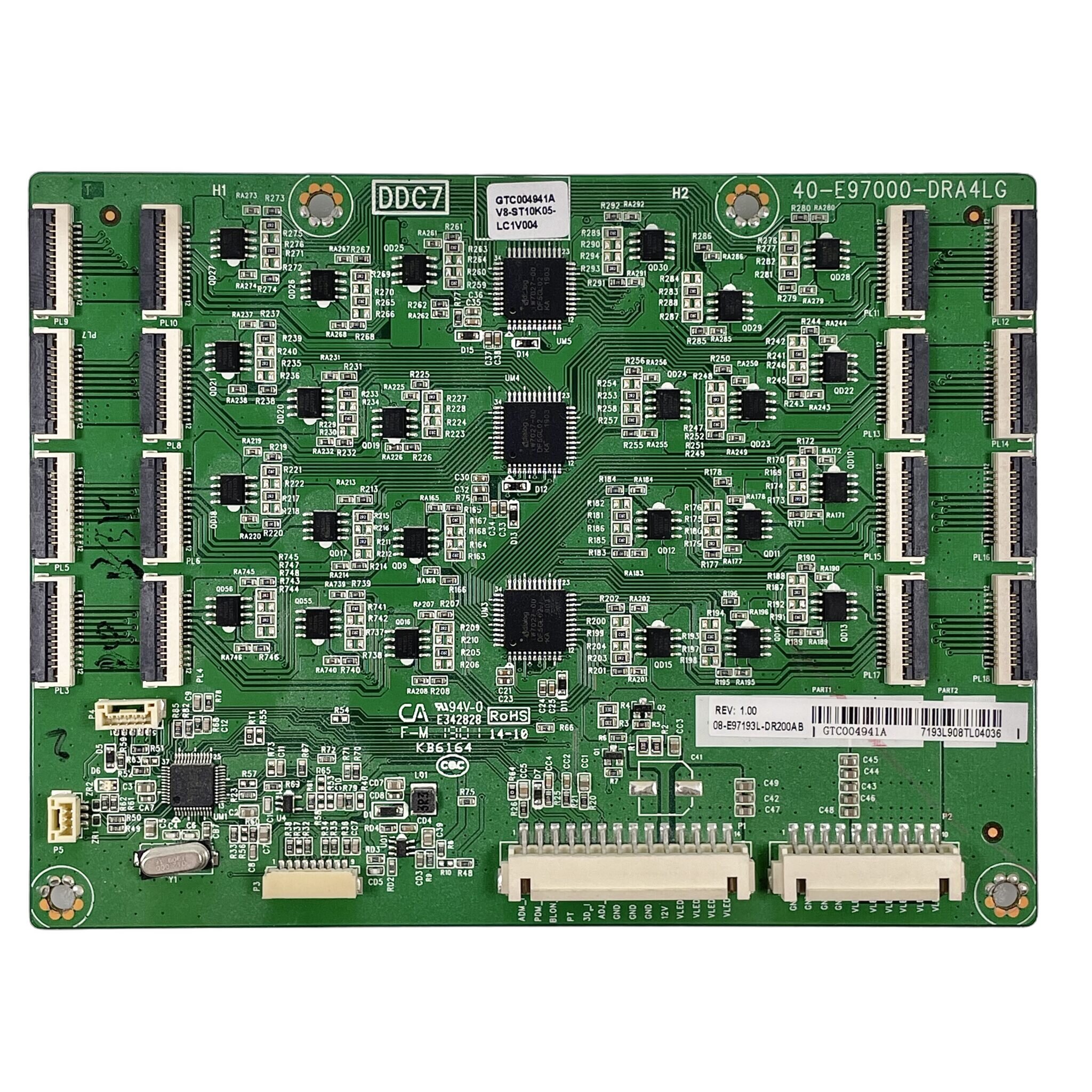
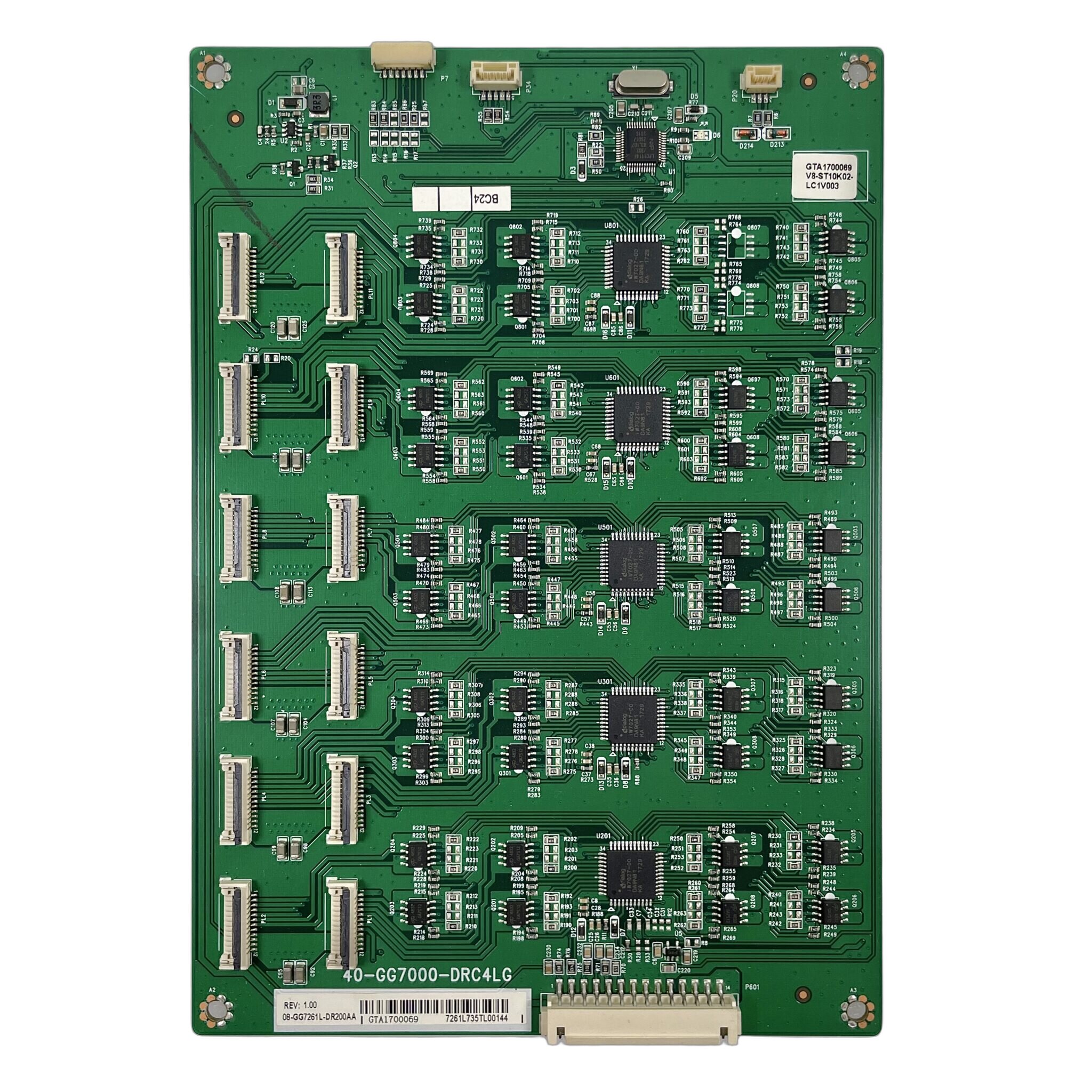
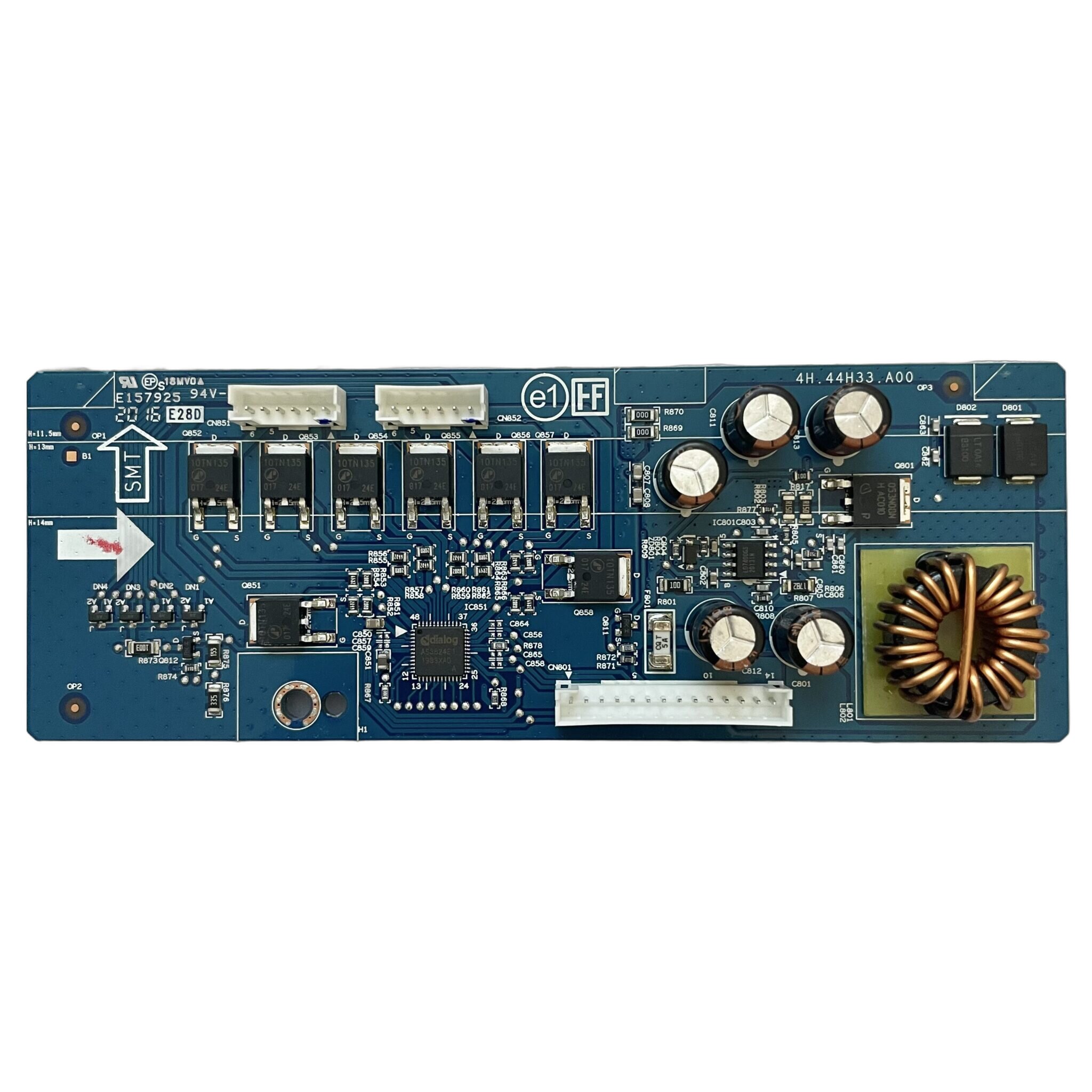
Also known as: Backlight Driver Board
What it does: The LED driver board regulates power to the backlight system of an LCD panel, ensuring consistent brightness and uniform illumination across the screen. It converts low-voltage signals from the mainboard into high-voltage pulses to drive rows or strings of LEDs mounted behind or along the edges of the panel.
By managing backlight intensity, the LED driver also enables features like dynamic dimming, contrast enhancement, and power-saving modes. A malfunctioning driver board can result in dim screens, flickering, uneven lighting, or a completely dark display even if the image and audio are still functioning properly.
How LED Driver Boards Work:
- Input Signal Handling:
- Digital Control Signal: Receives brightness control signals from the mainboard, typically through I2C or PWM signals.
- Power Management IC: Converts these control signals into the necessary voltage and current to power the LEDs at the correct intensity.
- Backlight Intensity Control:
- Dimmer Circuit: Modulates the current supplied to the LEDs, enabling dimming for power-saving or enhanced contrast.
- Pulse Width Modulation (PWM): Used for precise control of brightness levels by varying the duty cycle of the power supplied to the LEDs.
- Power Distribution:
- Current Regulation: Ensures each LED or string of LEDs receives the correct amount of current for uniform brightness.
- Voltage Conversion: Converts the mainboard’s low-voltage output to higher voltages required by the LEDs (e.g., 12V or 24V).
- Thermal Management:
- Heat Sinks or Thermal Pads: Often used on the LED driver board to dissipate heat generated during operation.
- Thermal Shutdown: Some LED driver ICs include over-temperature protection to prevent overheating and damage to the circuit.
- Output to LED Backlight:
- LED Driver Outputs: Provides current to each row or column of LEDs to produce uniform backlighting across the LCD panel.
- Constant Current Supply: Maintains consistent current through the LEDs to avoid brightness variation and ensure long-term reliability.
Symptoms of failure:
Dim or Uneven Backlight
- What you see: The screen may have noticeable areas with low brightness or uneven lighting, particularly in certain zones or corners of the screen.
- Possible causes on the LED Driver Board:
- Power Supply Issues: Inconsistent or insufficient voltage from the driver can cause uneven brightness across the LEDs.
- Faulty LED Strings: A damaged or malfunctioning LED string can cause uneven lighting or dark patches.
- Driver IC Failure: A defective driver IC may not regulate current properly, resulting in dim or non-functioning LEDs.
- How to diagnose:
- Measure output voltages: Check the voltage across LED strings to ensure proper power is being delivered.
- Inspect LEDs: Manually inspect or use a diagnostic tool to identify faulty LEDs within strings.
- Check for overheating: Excessive heat could indicate overdriving of the LEDs, which can cause uneven lighting.
Quick fix: Replacing or reflowing the LED driver board often resolves issues—ensure all LED strings are intact and free of damage.
Complete Loss of Backlight (Screen Black but Sound OK)
- What you see: The screen remains black despite the TV or monitor being powered on, and audio functions properly. No backlight is visible even when shining a flashlight on the screen.
- Possible causes on the LED Driver Board:
- Dead LED Driver IC: If the IC responsible for controlling the LED strings fails, no power will reach the backlight LEDs.
- Blown Fuse: A blown fuse on the LED driver board can interrupt power flow to the LEDs.
- Damaged Power Supply: If the power supply isn’t providing the correct voltage to the driver, the LEDs won’t light up.
- How to diagnose:
- Check for visible damage: Look for burnt components, especially on the driver IC and fuse.
- Measure voltages: Use a multimeter to check for voltage at the LED driver outputs.
- Check fuse continuity: Replace any blown fuses with the correct rating.
Quick fix: Replacing the LED driver board or the fuse often restores the backlight—ensure there is no short before powering on again.
Flashing or Pulsing Light
- What you see: The screen flashes or pulses intermittently, where the backlight fluctuates in brightness or blinks on and off.
- Possible causes on the LED Driver Board:
- PWM Dimming Issues: A fault in the PWM control signal may cause the LEDs to flicker or pulse due to improper dimming control.
- Power Supply Fluctuations: Inconsistent power delivery or voltage drops can result in flashing or pulsing backlight.
- Overheating or Overload: The driver may be overheating or overloaded, causing intermittent operation to prevent damage.
- How to diagnose:
- Measure power supply stability: Check if the voltage supplied to the LED driver is stable.
- Check PWM signals: Inspect the PWM signal for consistency and proper modulation.
- Inspect for heat buildup: Check for signs of overheating or thermal shutdown in the driver IC.
Quick fix: Replacing or reflowing the LED driver board often resolves issues—ensure power is stable and there is no excessive heat buildup.
Flickering or Strobing Backlight
- What you see: The backlight flickers or strobing occurs, typically in sync with changes in brightness or scene transitions.
- Possible causes on the LED Driver Board:
- PWM Dimming Circuit Failure: A failure in the dimming circuitry may cause rapid and inconsistent brightness shifts.
- LED Driver Circuit Instability: An unstable or faulty driver circuit may not properly control the backlight brightness.
- How to diagnose:
- Test PWM signals: Use an oscilloscope to check if the PWM dimming signals are stable.
- Inspect components: Look for any damaged or malfunctioning components on the driver circuit.
Quick fix: Replacing the LED driver or repairing the dimming circuitry can fix flickering or strobing issues.
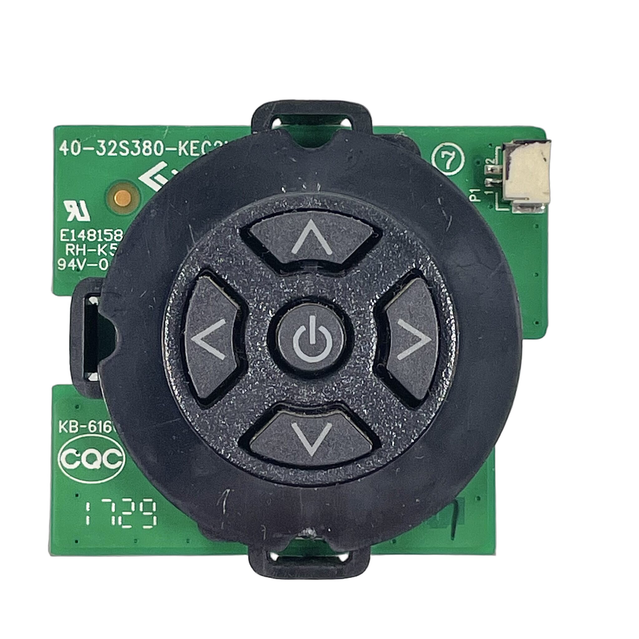
5. IR Sensor (TV IR Sensor)
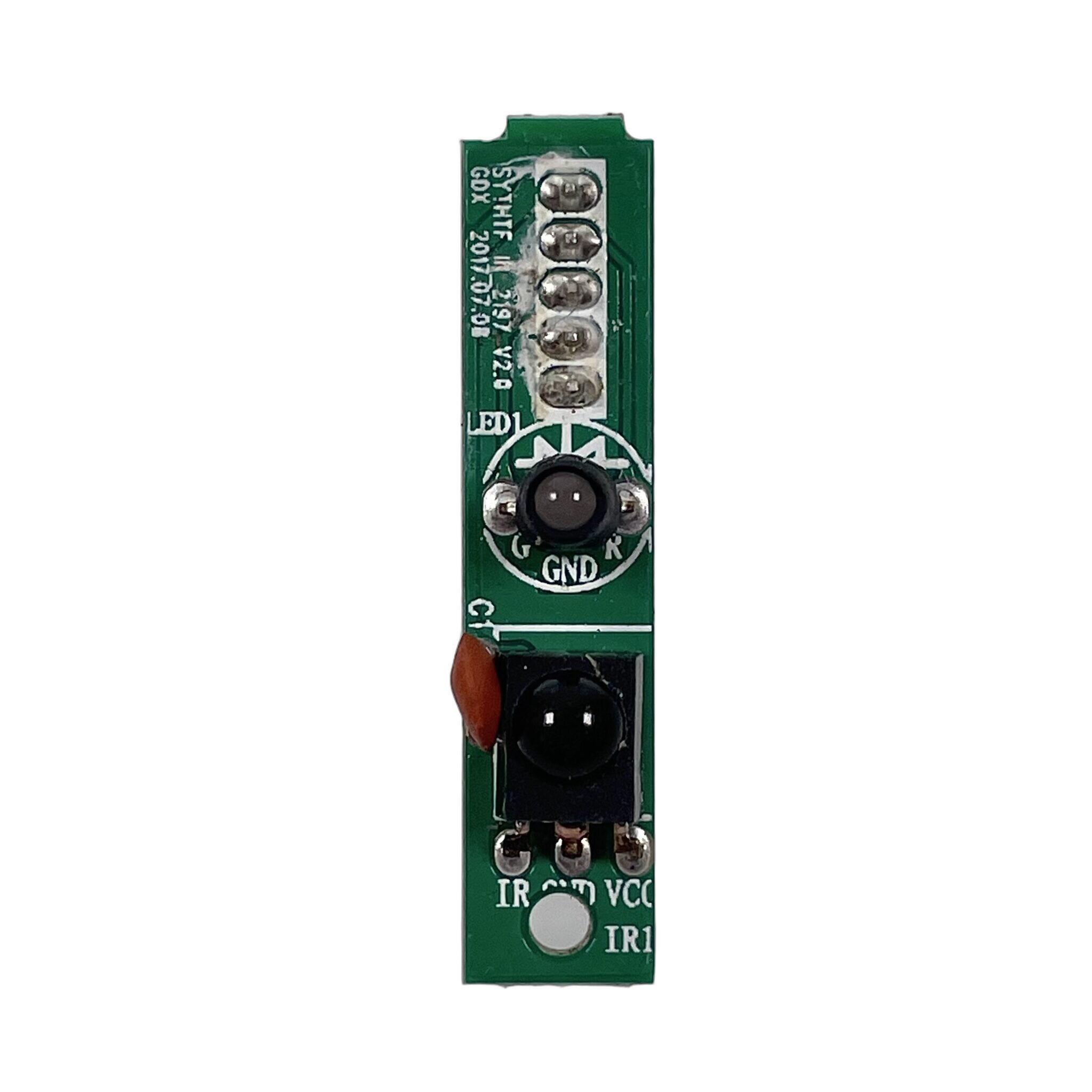
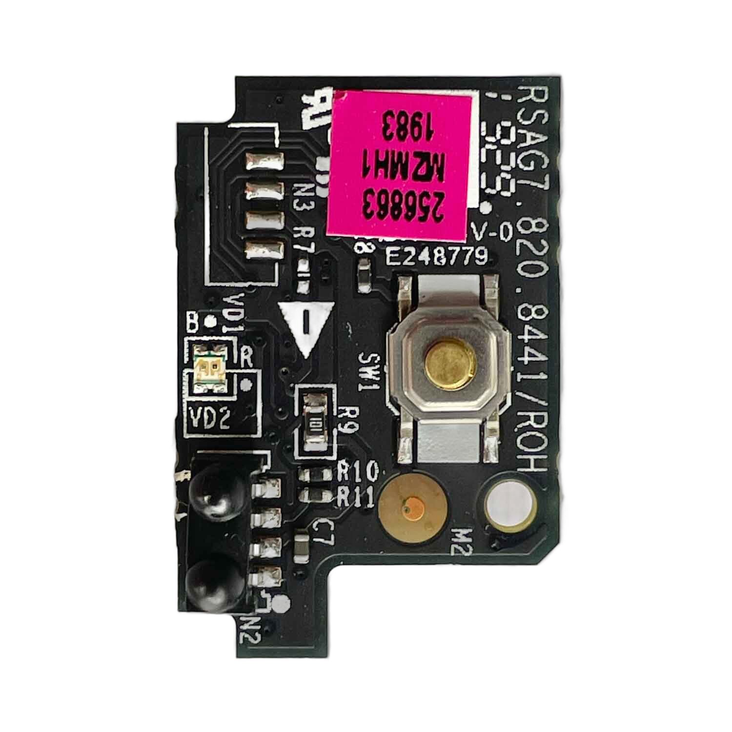
Also known as: Front Panel Board, IR Receiver
What it does: The Front Panel Board (also known as the IR Receiver) is responsible for receiving infrared (IR) signals from the remote control and passing these commands to the mainboard for processing. It acts as the interface between the user and the device, enabling remote control functionality to adjust settings such as volume, input, and power. Additionally, the IR board often features an LED indicator light, commonly referred to as the “ON display light,” which signals that the IR receiver is active and functioning.
In some designs, the IR sensor and the power or panel buttons may be integrated into the same board, streamlining the design and reducing the number of components.
How TV IR Sensors Work:
- Signal Reception:
- Infrared Light Detection: The IR sensor receives infrared light signals emitted from the remote control. The remote sends signals as light pulses modulated at specific frequencies.
- Optical Sensor: The IR sensor typically includes a photodiode or phototransistor that detects these light pulses and converts them into electrical signals.
- Signal Processing:
- Signal Decoding: The electrical signals are then passed to a decoder circuit that interprets the modulated IR signal, extracting the command (e.g., volume up, input change, power on/off).
- Microcontroller Interface: The decoded signals are sent to the microcontroller or mainboard, which processes the command and executes the corresponding action (e.g., turning on/off the TV, adjusting volume).
- Power Management:
- Power Supply: The IR sensor typically receives power from the TV’s mainboard, often regulated through a low-voltage power supply that ensures consistent functionality.
- Low Power Consumption: IR sensors are designed to consume minimal power, only activating when receiving an IR signal from the remote.
- Range and Directionality:
- Effective Range: TV IR sensors are usually designed to receive signals within a specific range, typically up to 5-10 meters, depending on the sensor and remote strength.
- Field of View: The IR sensor may have a wide or narrow field of view, determining the angle at which it can receive signals from the remote control.
- Integration with TV Functions:
- Communication with Mainboard: The IR sensor sends the decoded signals to the mainboard, which controls various TV functions based on the received commands.
- Feedback to User: In some cases, the TV may provide feedback (e.g., flashing a light on the sensor) to confirm receipt of the IR signal.
Symptoms of IR Sensor Failure:
No Response from the Device
- What you see: The device does not respond when the remote control buttons are pressed. The indicator light on the IR sensor may not turn on, or the device stays unresponsive.
- Possible causes:
- Faulty IR Sensor: The IR sensor may be damaged or malfunctioning, preventing it from detecting signals from the remote control.
- Remote Control Battery Issues: The remote control’s battery could be weak or dead, preventing it from sending a signal.
- Remote Control Malfunction: The remote control itself may be faulty, with internal issues preventing signal transmission.
- IR Sensor Blockage: The sensor’s line of sight may be obstructed by objects, dirt, or other interference.
- How to diagnose:
- Test with a different remote: Try using another remote control (if available) to rule out remote issues.
- Check remote with a camera: Use the camera on a smartphone to check if the remote’s IR LED is emitting a signal (you should see a faint light through the camera).
- Inspect the IR sensor: Make sure the sensor is not obstructed, clean, and aligned with the remote control.
- Check the power supply: Ensure the device is properly powered and connected to the correct input.
Quick fix: Replace the remote’s batteries if necessary. If the sensor is faulty, replacing the IR sensor or cleaning the lens may resolve the issue. If the remote is malfunctioning, consider replacing the remote.
Intermittent or Unreliable Response
- What you see: The device occasionally responds to remote signals but not consistently, or the response is delayed.
- Possible causes:
- Weak Remote Signal: Low battery power in the remote control may cause weak or inconsistent IR signal transmission.
- IR Sensor Interference: Other light sources or electronic devices may interfere with the IR signal, causing delays or dropouts.
- Faulty IR Sensor: The IR sensor may have a partial failure, causing intermittent operation.
- Out of Range: The remote control may be used at too great a distance or at an incorrect angle, making it hard for the sensor to receive the signal.
- How to diagnose:
- Change the batteries in the remote: Weak batteries are often the cause of intermittent signal reception.
- Check for environmental interference: Move the device away from other light sources or electronics that could be causing interference.
- Test range and alignment: Ensure the remote is within the effective range of the sensor and pointed directly at the sensor.
Quick fix: Replace the remote’s batteries and check for any potential sources of interference. If the sensor is the issue, consider replacing it or adjusting its alignment.
Unresponsive Buttons on the Remote
- What you see: Specific buttons on the remote control fail to work, or the entire remote stops working intermittently.
- Possible causes:
- Remote Control Malfunction: The remote may have a malfunctioning button or internal circuitry problem.
- Battery Issues: Low or inconsistent battery power can cause certain buttons to stop responding.
- Signal Interference: Environmental factors or interference from other devices may disrupt the IR signal.
- How to diagnose:
- Test remote on another device: Try using the remote on a different device to see if the issue persists.
- Inspect the buttons: Ensure none of the buttons are physically stuck or damaged.
- Check battery voltage: Replace the batteries with fresh ones to rule out weak power.
Quick fix: Replace the batteries in the remote and inspect the buttons for damage. If the problem persists, consider replacing the remote.
Device Power Cycles or Turns Off Unexpectedly
- What you see: The device turns off or restarts unexpectedly when the remote control is used.
- Possible causes:
- IR Sensor Power Supply Issues: A power fluctuation in the IR sensor circuit can cause instability, resulting in power cycling.
- Remote Signal Interference: Other devices emitting IR signals may interfere with the remote control, causing the device to turn off or reset.
- Faulty Remote Control: A malfunctioning remote may send random or conflicting signals, causing the device to power cycle.
- How to diagnose:
- Test with a different remote: Try using another remote control to see if the issue is specific to the original remote.
- Check for environmental interference: Move the device away from other electronics or IR-emitting devices that could cause interference.
- Inspect the device power supply: Check for any issues with the power supply or connections to ensure stable power delivery.
Quick fix: Replacing or resetting the remote may fix the issue, along with ensuring there is no interference in the environment. If the sensor is at fault, replacing it may resolve the power cycling issue.
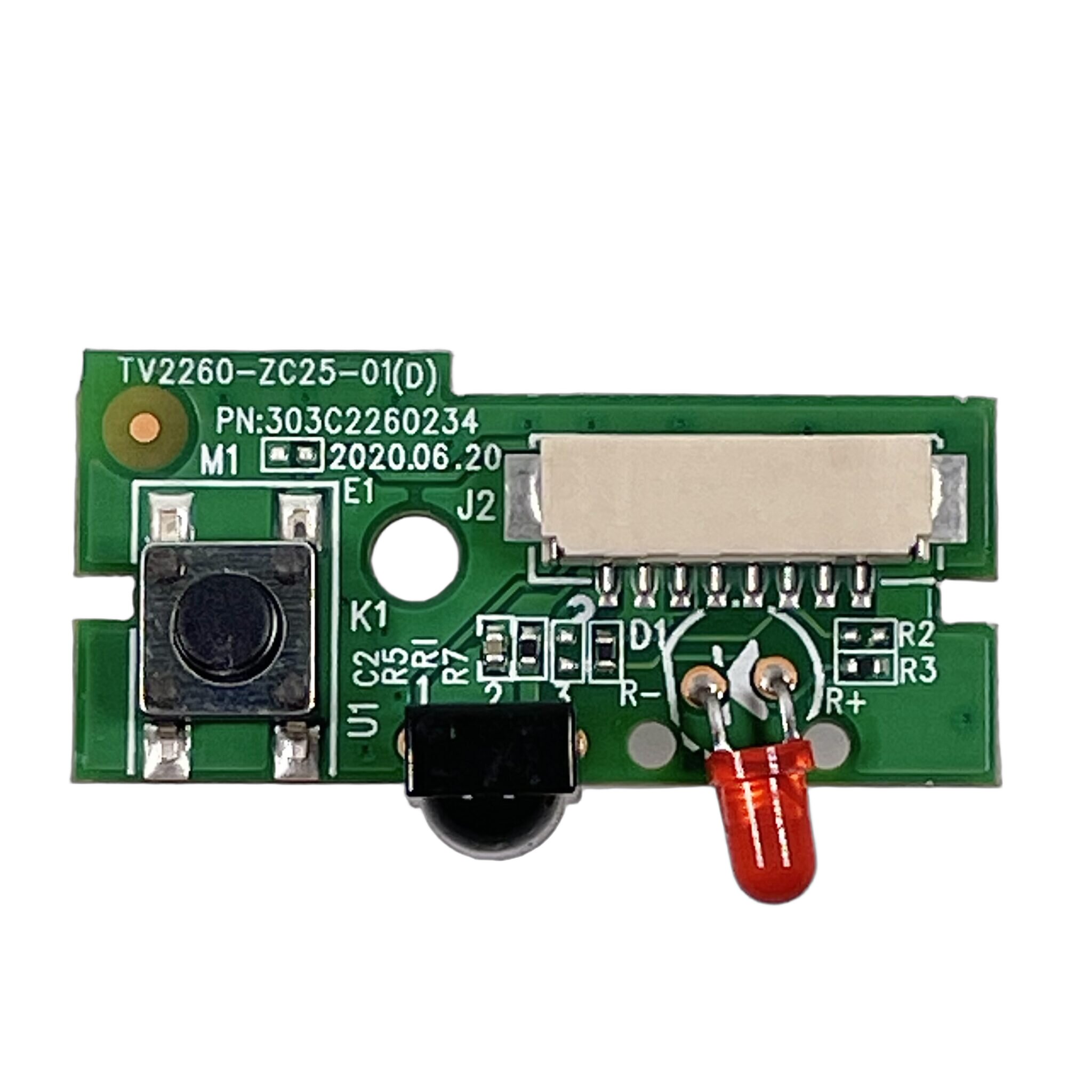
6. Button Board (TV Power/Panel Buttons)
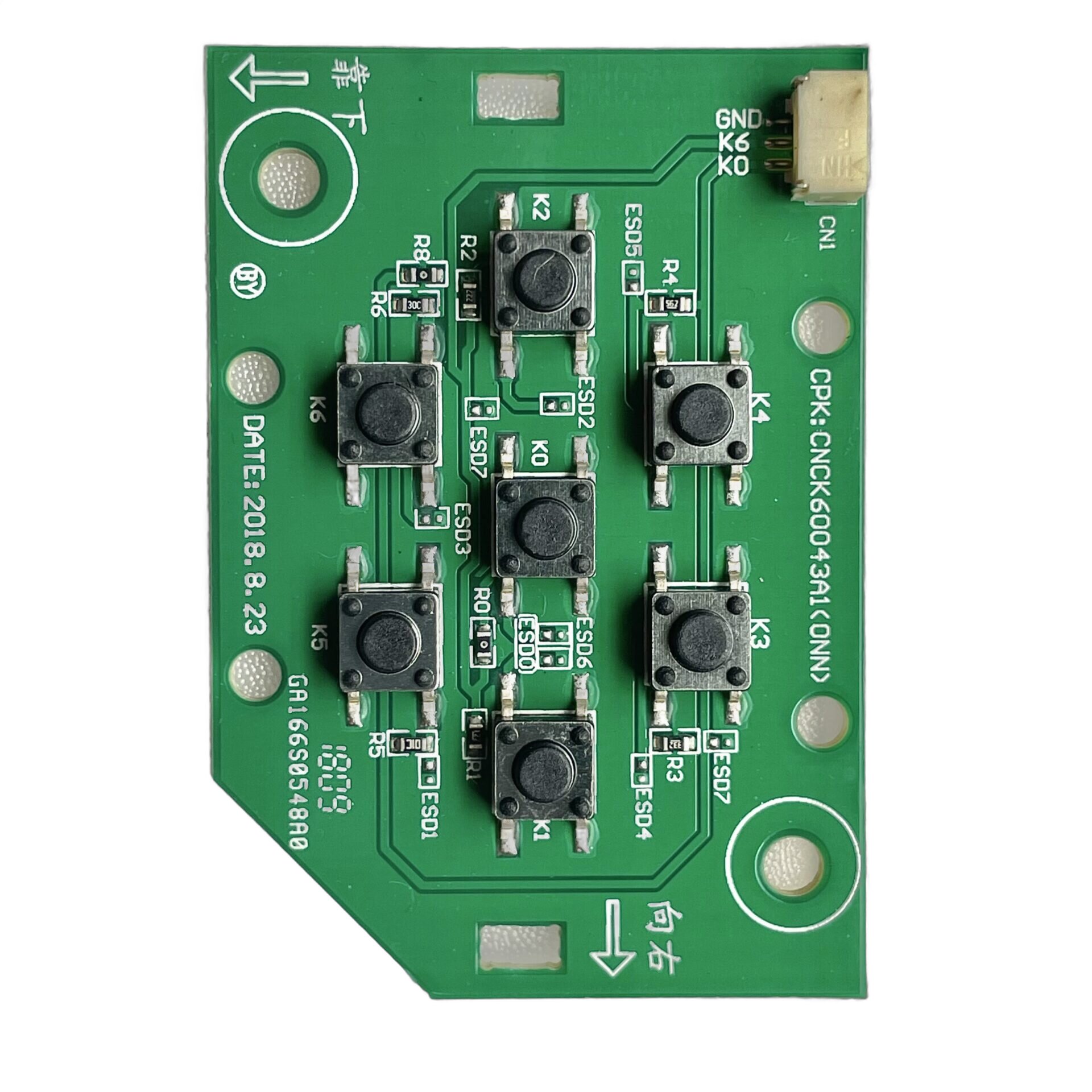
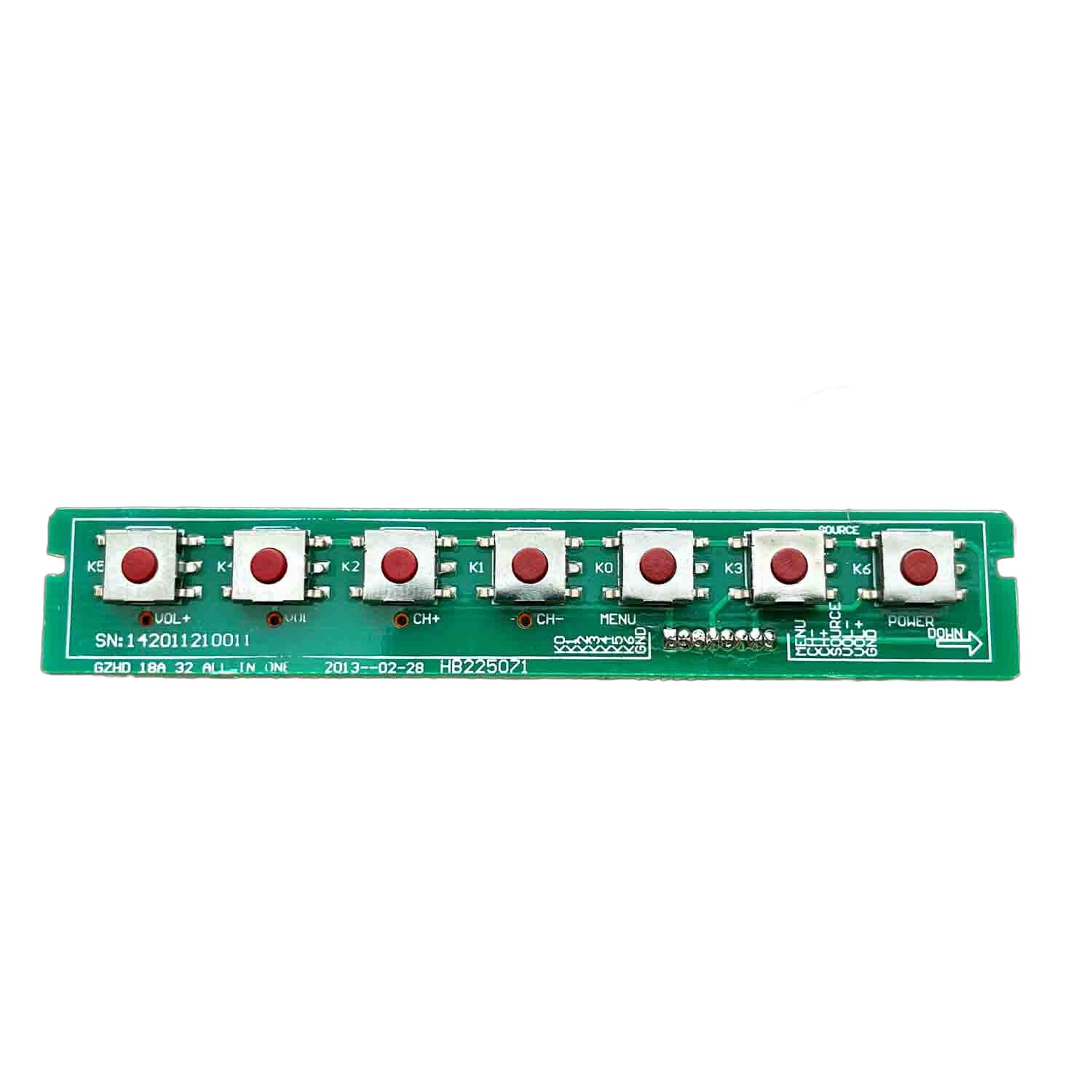
Also known as: Power Button, Control Buttons, Front Panel Buttons
What it does: The panel buttons are physical controls located on the front or sometimes the back of the TV, allowing users to adjust settings manually without the remote control. These buttons typically include functions such as power on/off, volume control, input selection, and menu navigation. They provide an alternative means of controlling the TV when the remote is unavailable or out of reach.
In some designs, the power or panel buttons and the IR sensor may be integrated into the same board, streamlining the design and reducing the number of components. The integration of these components helps optimize the TV’s user interface while maintaining a clean, functional layout.
How TV Panel/Power Buttons Work:
- Button Activation:
- Physical Press: The panel/power buttons are activated when the user physically presses them, which typically completes an electrical circuit within the button mechanism.
- Signal Generation: When pressed, the button sends a signal to the internal circuit or microcontroller that processes the command (e.g., turning the TV on/off, adjusting volume).
- Signal Transmission:
- Internal Circuit Communication: The button sends the signal to a microcontroller or dedicated controller on the TV’s mainboard, which interprets the action and triggers the corresponding function.
- Power Button Feedback: If the power button is pressed, it typically sends a signal to power on/off the TV, and the TV may provide visual feedback such as an LED indicator lighting up or flashing.
- Power Management:
- Power Supply: The panel/power buttons rely on the TV’s mainboard for power and function.
- Low Voltage Activation: The power buttons generally operate at low voltage and are designed to be energy-efficient in responding to user inputs.
- Integration with IR Sensors:
- Combined Functionality: In some designs, the panel buttons and the IR sensor are integrated on the same board, streamlining the design by allowing both functionalities to share the same power and data connection.
- Alternate Input: If the remote control is unavailable, the panel/power buttons serve as a backup input for controlling the TV directly.
Symptoms of Panel/Power Button Failure:
No Response from the Device
- What you see: The device does not respond when the power or panel buttons are pressed. The indicator light may not turn on, or the TV stays unresponsive.
- Possible causes:
- Faulty Button Mechanism: The button’s internal contacts may be damaged or worn out, preventing the button from completing the circuit.
- Wiring Issues: There may be a broken or loose wire connection between the button and the mainboard, preventing signal transmission.
- Malfunctioning Microcontroller: The TV’s microcontroller may fail to process the signal sent by the power button, resulting in no response.
- Button Blockage: Dirt or debris may block the button’s mechanical or electrical contacts, causing it to become unresponsive.
- How to diagnose:
- Test the button press: Press the button multiple times to check if there is a mechanical failure or sticking.
- Inspect the wiring: Look for any visible signs of loose or damaged wires leading to the button.
- Check for debris: Ensure the button is clean and free from dirt or debris that could obstruct the internal contacts.
- Test with a remote: Use a remote control to check if the device is responding, indicating that the issue is with the button itself.
Quick fix: If the button mechanism is faulty, it may need to be replaced. Cleaning any debris around the button or reconnecting wires could restore functionality.
Intermittent Response from the Button
- What you see: The device occasionally responds when the panel/power button is pressed, but not consistently or with a delay.
- Possible causes:
- Worn Button Contacts: The button’s internal contacts may have become worn, resulting in unreliable signal transmission.
- Loose Wiring: A loose connection between the button and mainboard may cause intermittent response.
- Faulty Button Mechanism: The button may be physically damaged, causing inconsistent electrical contact when pressed.
- How to diagnose:
- Test button pressure: Apply varying pressure to the button to check for inconsistent behavior.
- Inspect wiring: Check for loose or intermittent wire connections between the button and mainboard.
- Clean the button: Clean the area around the button to ensure there are no obstructions affecting the mechanism.
Quick fix: Cleaning or adjusting the wiring could solve the intermittent issue. Replacing the button may be necessary if the contacts are too worn.
Button Sticking or Not Pressing Properly
- What you see: The power/panel button is physically stuck or does not press down smoothly, possibly requiring extra force to activate.
- Possible causes:
- Debris or Dirt: Dirt or debris could be lodged under the button, preventing it from pressing properly.
- Worn or Damaged Button Mechanism: The internal spring or contacts of the button may be damaged, causing it to stick or not respond.
- Button Misalignment: The button may be misaligned with the housing, causing it to become stuck when pressed.
- How to diagnose:
- Check for debris: Look around the button for dirt or other obstructions that may be causing it to stick.
- Inspect button mechanism: Press the button repeatedly to check for smoothness and signs of wear or misalignment.
- Remove panel casing: If safe to do so, remove the casing around the panel to check for internal damage or misalignment of the button.
Quick fix: Cleaning around the button may resolve the issue. If the button is damaged, it may need to be replaced or realigned.
Button Pressed but Device Doesn’t Turn On/Off
- What you see: The power/panel button is pressed, but the device does not turn on or off as expected.
- Possible causes:
- Faulty Button Contacts: The internal contacts of the button may be damaged, causing the button to press without completing the necessary circuit.
- Power Supply Issue: The TV may not be receiving proper power, preventing it from turning on/off even if the button is pressed.
- Microcontroller Failure: The microcontroller may fail to process the button signal, preventing the device from responding.
- How to diagnose:
- Check power supply: Ensure the TV is properly connected to power and the outlet is functioning.
- Test with remote: If the remote can turn the device on/off, it suggests the button is the issue.
- Inspect button contacts: Look for signs of wear or damage to the button’s internal contacts.
Quick fix: If the button contacts are damaged, replacement may be necessary. If the power supply is faulty, check connections or reset the device.
7. WiFi Module & Smart TV Boards (TV WiFi)
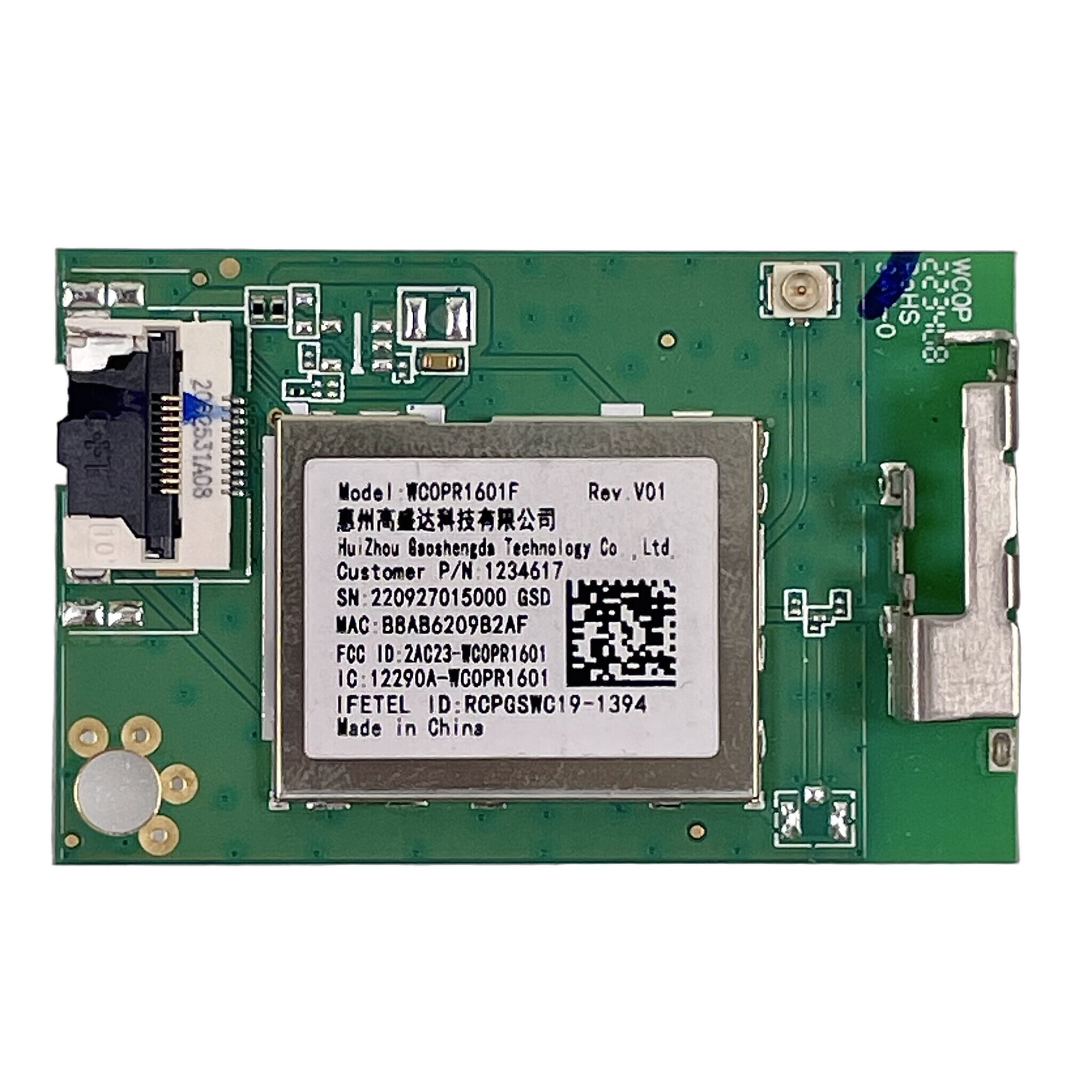
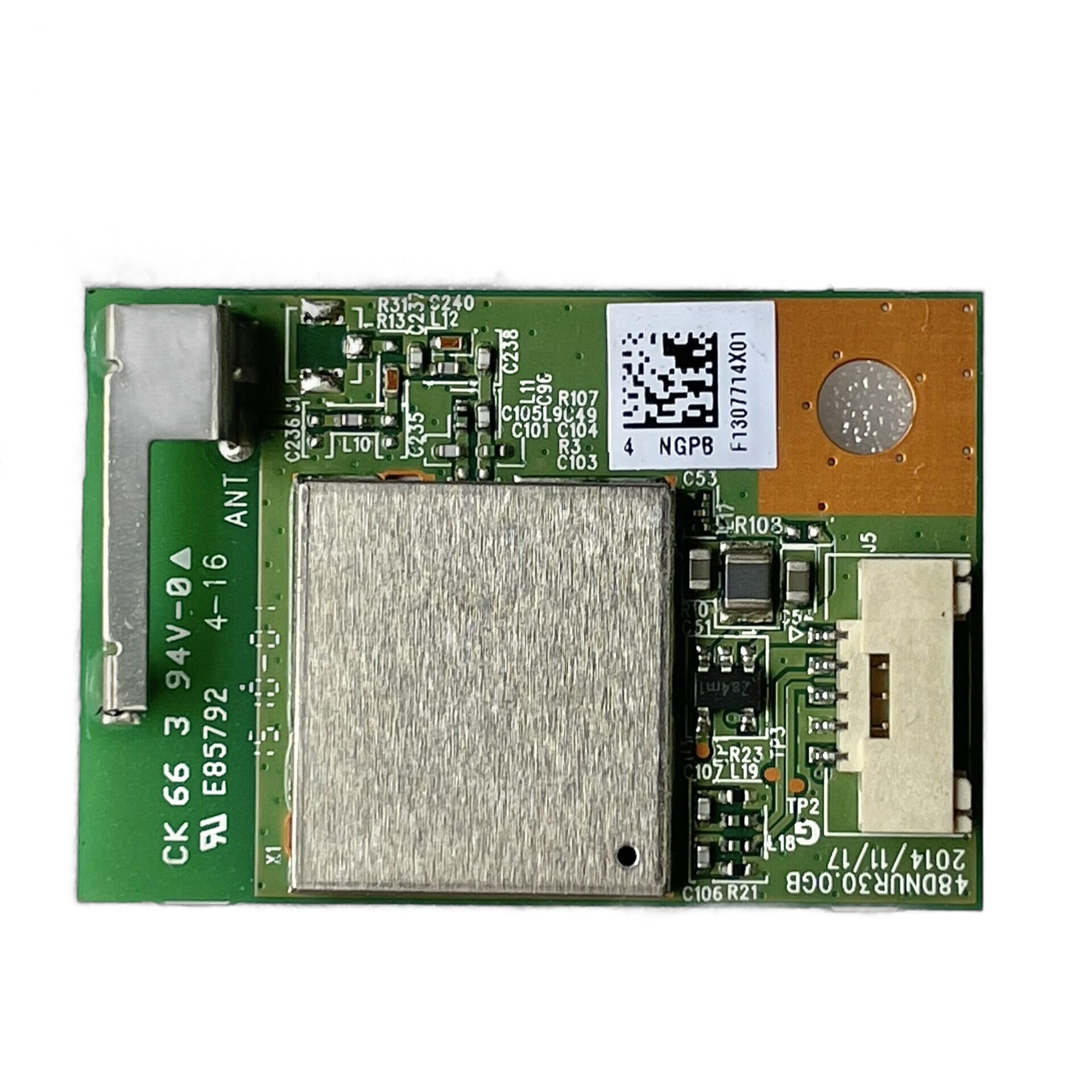
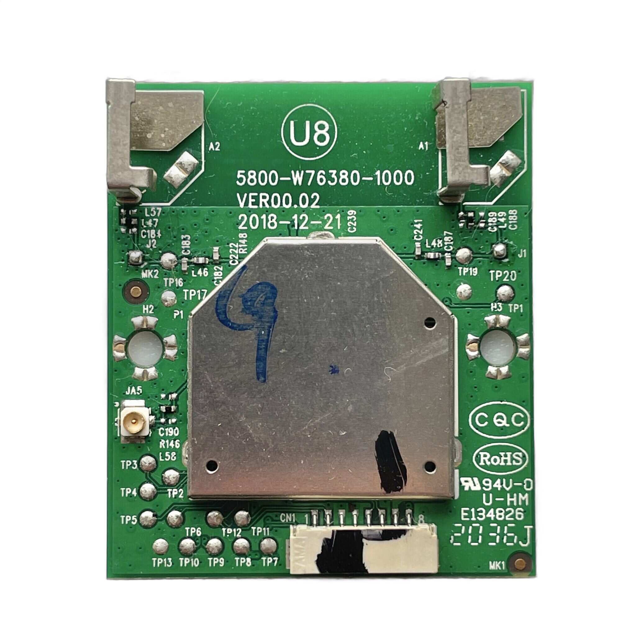
Also known as: Wireless Module, Smart Module
What it does: The wireless module enables connectivity for streaming apps, firmware updates, and screen-mirroring on compatible devices. It provides the essential link between the TV and the internet or other wireless devices, allowing users to stream content from apps like Netflix, YouTube, or Spotify, perform automatic software updates, and wirelessly mirror the screen of a smartphone, tablet, or computer onto the TV. This enhances the TV’s functionality and flexibility without the need for additional physical connections.
The wireless module is typically integrated into the TV’s internal circuitry and is designed to work seamlessly with the TV’s smart features. It supports various wireless technologies such as Wi-Fi and Bluetooth, enabling communication with a wide range of devices for a more interactive and dynamic viewing experience.
How Wi-Fi Modules Work:
- Module Activation:
- Power-Up: The Wi-Fi module is powered on when the TV is switched on, activating the internal circuitry that manages wireless communication.
- Signal Detection: Once powered, the module starts searching for available Wi-Fi networks, typically by scanning for wireless signals in the surrounding area.
- Signal Transmission:
- Network Connection: The Wi-Fi module communicates with the TV’s microcontroller to initiate a connection with a selected wireless network. This communication ensures the TV is able to access the internet or local network for streaming, updates, and other services.
- Data Exchange: Once connected, the module sends and receives data packets to and from the TV’s processor, facilitating actions like streaming video, updating firmware, or accessing apps.
- Communication with Other Devices:
- Data Flow: The Wi-Fi module enables two-way communication between the TV and other wireless devices, such as smartphones or tablets, supporting features like screen mirroring and content sharing.
- Protocol Support: The module typically supports various Wi-Fi standards (e.g., Wi-Fi 5, Wi-Fi 6) to ensure compatibility with modern routers and networks for fast, stable connections.
- Power Management:
- Low Power Consumption: The Wi-Fi module is designed to use minimal power during operation, contributing to the TV’s overall energy efficiency while maintaining constant network connectivity.
- Auto Sleep Mode: To conserve power, the module may enter a low-power sleep mode when not in use, such as during idle times or when the TV is off.
- Security and Encryption:
- Encryption: The Wi-Fi module ensures secure communication by supporting encryption protocols like WPA2, protecting data transmission between the TV and the network from unauthorized access.
- Network Authentication: The module authenticates the TV’s connection to the wireless network, ensuring that only authorized devices can join the network for safety and privacy.
Symptoms of Wi-Fi Module Failure:
No Connection to Wi-Fi
- What you see: The device fails to connect to the Wi-Fi network. The TV may show no available networks, or it cannot establish a connection despite being in range of the router.
- Possible causes:
- Faulty Wi-Fi Module: The Wi-Fi module itself may have malfunctioned or failed, preventing it from detecting or connecting to the network.
- Router Issues: There may be issues with the router, such as incorrect settings, interference, or an unstable connection.
- Software Glitch: The TV’s software or firmware may be out of date or experiencing a bug, preventing it from properly connecting to the network.
- How to diagnose:
- Test other devices: Check if other devices can connect to the same Wi-Fi network to rule out router or internet issues.
- Restart the TV: Reboot the TV to clear potential software glitches.
- Check for software updates: Ensure the TV is running the latest software/firmware that might address Wi-Fi issues.
Quick fix: If the Wi-Fi module is faulty, replacement may be necessary. A software update or router reset could resolve some connection issues.
Weak or Unstable Wi-Fi Connection
- What you see: The TV connects to the Wi-Fi network, but the connection is weak or keeps dropping. Streaming and app performance may be affected.
- Possible causes:
- Interference: Other devices or physical obstructions between the TV and router may cause signal interference, leading to weak performance.
- Router Settings: The router may be configured incorrectly, or the Wi-Fi signal may be overloaded, especially if there are multiple devices connected.
- Wi-Fi Module Malfunction: The Wi-Fi module may have a hardware issue that affects the signal strength or stability.
- How to diagnose:
- Move closer to the router: Ensure the TV is within a reasonable range of the router to improve signal strength.
- Check for interference: Identify if other devices or obstructions could be causing signal interference.
- Test with a wired connection: Try connecting the TV directly to the router with an Ethernet cable to check if the issue is with the Wi-Fi connection itself.
Quick fix: Adjusting the router’s position or settings, reducing interference, or replacing the Wi-Fi module may resolve connection instability.
Wi-Fi Module Not Detected
- What you see: The TV does not recognize the Wi-Fi module, or the Wi-Fi settings menu does not appear.
- Possible causes:
- Loose Connections: The Wi-Fi module may not be properly connected to the mainboard, preventing it from being detected.
- Faulty Module: The Wi-Fi module may have failed completely and is no longer operational.
- Firmware Issue: A corrupted or outdated firmware may prevent the TV from detecting the Wi-Fi module.
- How to diagnose:
- Check physical connections: Inspect the connections of the Wi-Fi module to ensure it is securely attached to the TV’s mainboard.
- Perform a factory reset: If the issue persists, performing a factory reset may resolve software-related detection problems.
- Update firmware: Ensure the TV’s firmware is up to date to fix potential bugs that prevent Wi-Fi detection.
Quick fix: Re-securing connections or updating the firmware might restore functionality. If the module itself is faulty, replacing it may be necessary.
Wi-Fi Module Overheating
- What you see: The TV experiences intermittent Wi-Fi drops or the Wi-Fi module becomes unresponsive after prolonged use, possibly accompanied by unusual heat or the module’s LED indicator turning off.
- Possible causes:
- Insufficient Ventilation: Poor ventilation around the Wi-Fi module can lead to overheating, affecting its performance.
- Defective Module: A malfunctioning Wi-Fi module may overheat due to internal component failure.
- Power Surge: A surge of power could have damaged the module’s internal circuits, leading to overheating.
- How to diagnose:
- Check for overheating: Gently feel the Wi-Fi module area to check for abnormal heat buildup.
- Ensure proper ventilation: Make sure there is enough space around the TV to allow heat dissipation.
- Test after cooling: Turn off the TV and let it cool for an hour, then check if the Wi-Fi connection returns to normal.
Quick fix: Ensure proper ventilation and check for signs of overheating. If the module is defective, it may need to be replaced.
8. AC Power Cord (TV Power Cable)
Also known as: Power Cable, Power Cord, AC Power Cable
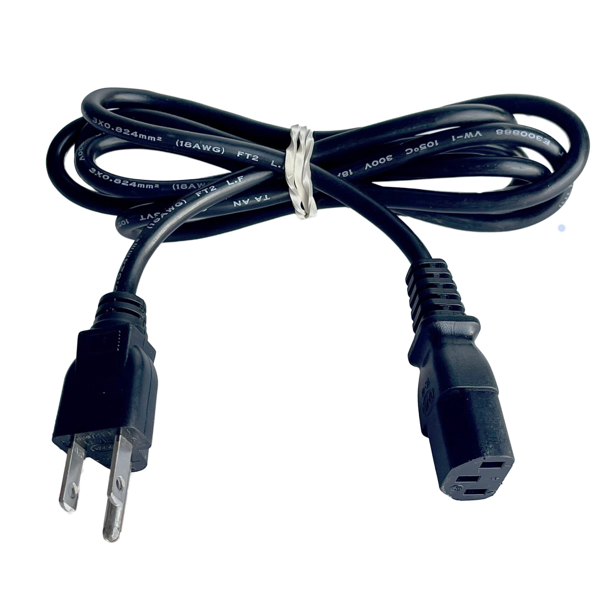
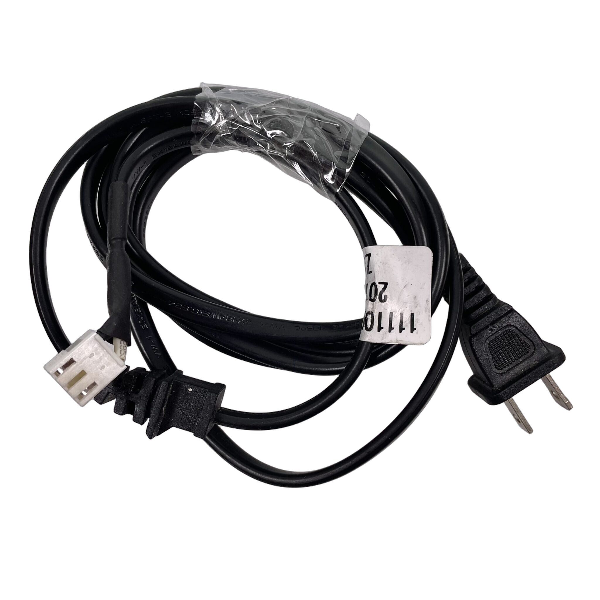
What it does: The TV power cable/cord provides electrical power to the TV by connecting it to an electrical outlet. It is an essential component for the TV’s operation, allowing the internal circuits and display to function properly. The cable is usually designed to accommodate the specific power requirements of the TV, ensuring safe and efficient power delivery. Some TVs use an internal power cable that connects directly to the power supply unit (PSU) inside the TV. This type of cable clips onto the power board and is not removable from the back of the TV, meaning the unit must be disassembled to remove or replace it.
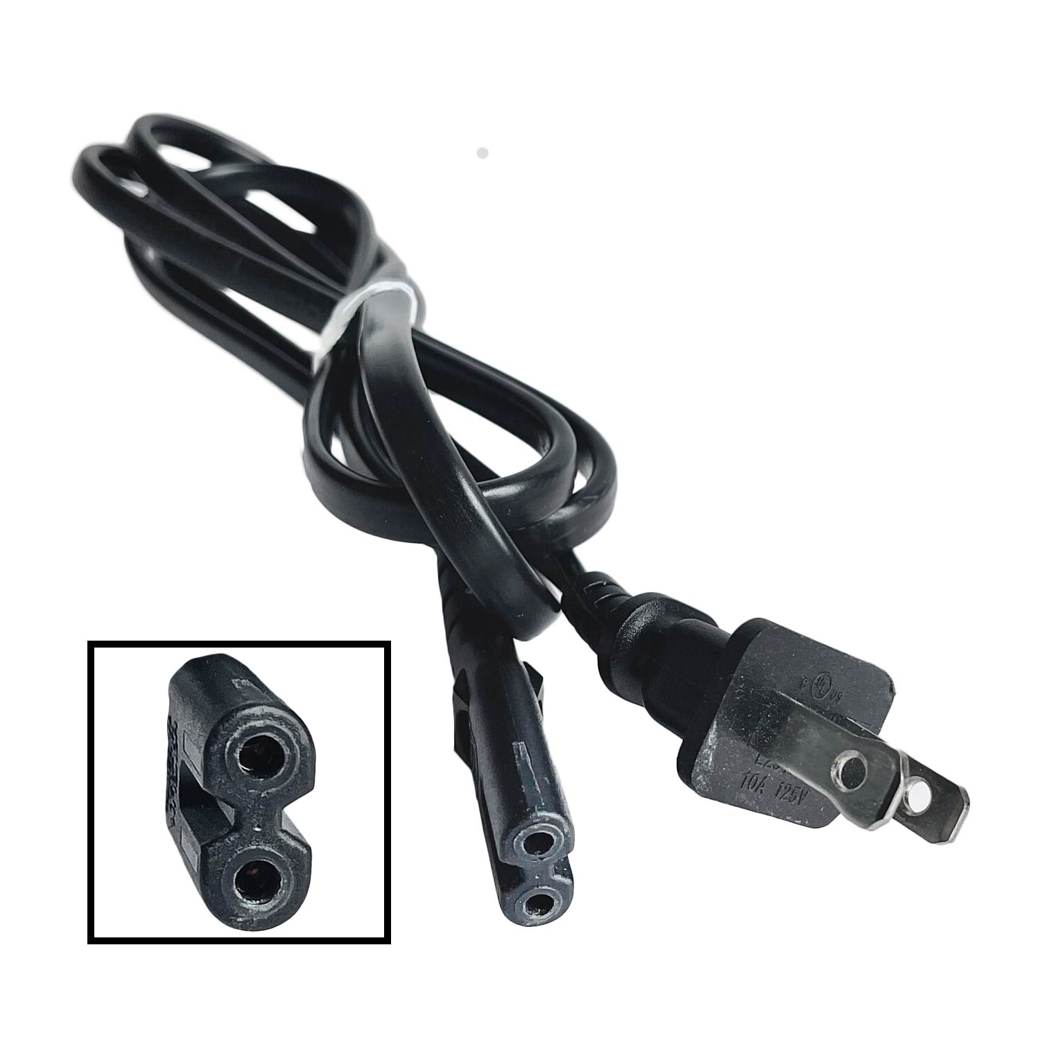
In North America, there are four main types of power connectors used for TVs: the IEC 320 C13 (three-prong), which provides a grounded connection for added safety; the IEC 320 C7 (two-prong non-polar), typically used for smaller or older models; the IEC 320 C7 polarized (two-prong), where one prong is wider to ensure the correct orientation for power flow; and internal PSU-connected cables, which are clipped directly onto the power board and require TV disassembly for replacement. These connectors ensure compatibility with various TVs and offer reliable power connections for different models and use cases.
How Power Cords Work:
- Power Delivery:
- Connection to Outlet: The power cord connects the TV to an electrical outlet, enabling the flow of alternating current (AC) power from the wall socket to the TV.
- Power Transfer: When the TV is turned on, the power cord transfers the electrical energy to the internal power supply of the TV, which then converts it to the appropriate voltage for the TV’s operation.
- Types of Cords:
- IEC 320 C13 (Three-Prong): The three-prong cord has a grounding pin that helps prevent electrical shock and ensures safe operation of the TV.
- IEC 320 C7 (Two-Prong Non-Polarized): This cord type has two prongs of equal size, typically used for smaller TVs, and does not offer polarity, making it less secure compared to the three-prong version.
- IEC 320 C7 (Two-Prong Polarized): This version has one wider prong to ensure proper orientation of the cord when connected, ensuring the correct flow of electricity into the TV.
- Internal PSU-Connected Cable: Some TVs use a power cable that connects directly to the internal power board and clips onto the power supply unit inside the TV. These cables are not detachable from the outside and require disassembly of the TV to access or replace them.
- Internal Power Conversion:
- Voltage Regulation: The power cord provides the necessary input to the TV’s internal power supply unit, which regulates the voltage and ensures the correct power is delivered to the TV’s circuits and components.
- Safety Features: The power cord ensures a safe power connection, preventing over-voltage, short circuits, and other potential hazards from affecting the TV.
- Power Management:
- Energy Efficiency: Once connected, the TV manages its power usage, reducing consumption when idle or turned off, depending on the TV’s settings and features.
- Power-Off: When the TV is turned off, the power cord no longer delivers energy to the device, ensuring it does not consume power unnecessarily.
Symptoms of Power Cord Failure:
No Power to the TV
- What you see: The TV does not power on when the power button is pressed. The screen remains blank, and no indicator lights turn on.
- Possible causes:
- Broken Power Cord: The power cord may be damaged, preventing electrical power from reaching the TV.
- Loose Connection: The power cord might not be securely plugged into the outlet or the TV’s power input.
- Faulty Outlet: The electrical outlet may not be functioning properly, preventing power from being supplied.
- How to diagnose:
- Check power connection: Ensure the power cord is fully plugged into both the TV and the outlet.
- Test the outlet: Plug another device into the same outlet to confirm the outlet is working.
- Inspect the power cord: Look for visible signs of wear or damage on the power cord.
Quick fix: Try plugging the TV into a different outlet or replacing the power cord if it’s visibly damaged.
Intermittent Power Loss
- What you see: The TV powers off unexpectedly or has trouble staying on. The screen may flicker or turn off during operation.
- Possible causes:
- Loose Connection: The power cord may not be making a secure connection, causing the TV to lose power intermittently.
- Damaged Power Cord: A frayed or broken power cord can result in unstable power delivery to the TV.
- Faulty Power Outlet: An outlet that is not supplying consistent power can lead to intermittent power loss.
- How to diagnose:
- Secure the connection: Ensure the power cord is securely plugged into both the TV and the outlet.
- Test another outlet: Try plugging the TV into a different outlet to see if the issue persists.
- Inspect the cord: Look for visible damage or fraying on the power cord that could cause power disruptions.
Quick fix: Tightening the connection or replacing a damaged power cord should resolve intermittent power loss.
Power Cord Overheating
- What you see: The power cord or the area near the TV’s power input becomes hot to the touch during use. There may be a burning smell or discoloration on the cord.
- Possible causes:
- Overloaded Circuit: The power cord may be drawing more current than it is rated for, causing it to overheat.
- Damaged Cord: Internal wiring in the power cord may be short-circuiting, generating heat.
- Poor Ventilation: Insufficient airflow around the power cord and TV may lead to excessive heat buildup.
- How to diagnose:
- Check the cord for damage: Inspect the power cord for any visible wear, fraying, or discoloration.
- Check the outlet: Ensure that the outlet is not overloaded with other devices that may be drawing excessive power.
- Ensure proper ventilation: Make sure the area around the TV and cord is well-ventilated to avoid heat buildup.
Quick fix: If the cord is damaged, replace it. Ensure that the outlet is not overloaded and that the area around the cord has sufficient ventilation.
Power Cord Short Circuit
- What you see: The TV fails to power on, and the circuit breaker trips. You may also hear a popping sound or see sparks near the power connection.
- Possible causes:
- Frayed Wiring: Exposed wires in the power cord may touch each other, causing a short circuit.
- Faulty Outlet: An electrical issue in the outlet can cause the cord to short out when plugged in.
- Defective Power Cord: A manufacturing defect in the power cord could lead to a short circuit.
- How to diagnose:
- Inspect the cord: Check for visible signs of damage or exposed wiring on the power cord.
- Check the breaker: Ensure that the circuit breaker is not tripped and reset it if necessary.
- Test with another cord: Try using a different power cord to see if the issue persists.
Quick fix: Replace the damaged power cord or try a different outlet to avoid further short circuits.
How to Identify Compatible TV Parts for Your Model
- Check the model number (usually on a sticker at the back).
- Match board part numbers printed on the PCB.
- Compare connector types (ribbon cables, plugs).
Now that you’ve seen what goes into an LED TV and how each component plays a role, you’re better equipped to identify issues, choose the right replacement parts, and get your TV back up and running. With the right know-how and a little DIY spirit, you’ll be back to enjoying your favorite shows in no time.
Leave a Reply